HOW TO REPAIR AND INSTALL CYCLE Circuit Diagram The article presents a circuit that can be used for indicating the riding speed of a bicycle. The circuit of a bicycle speedometer explained here uses ordinary components like transistors and LEDs and yet succeeds in displaying a distinct 10 step, accurately calibrated linear reading, corresponding to the instantaneous speed of the bicycle wheels. The source is basically derived from a dynamo

What is a Bicycle Speedometer, How it Works. Bicycle speedometer is a device which checks the rotation per minute of the bicycle wheel and displays the results over a meter to indicate how fast the bicycle is travelling. Basically, a bicycle speedometer works in the following manner: A sensor is installed on the one of the wheels of the bicycle.

Precision Bicycle Speedometer Circuit using Hall Effect Sensors Circuit Diagram
I then take that information and compile it into a language that is super easy to understand. My goal is to make those complex electronics circuit concepts and technical terms much more accessible for all the new and budding electronics engineers out there. I can also design customized circuit diagrams as required by the users.

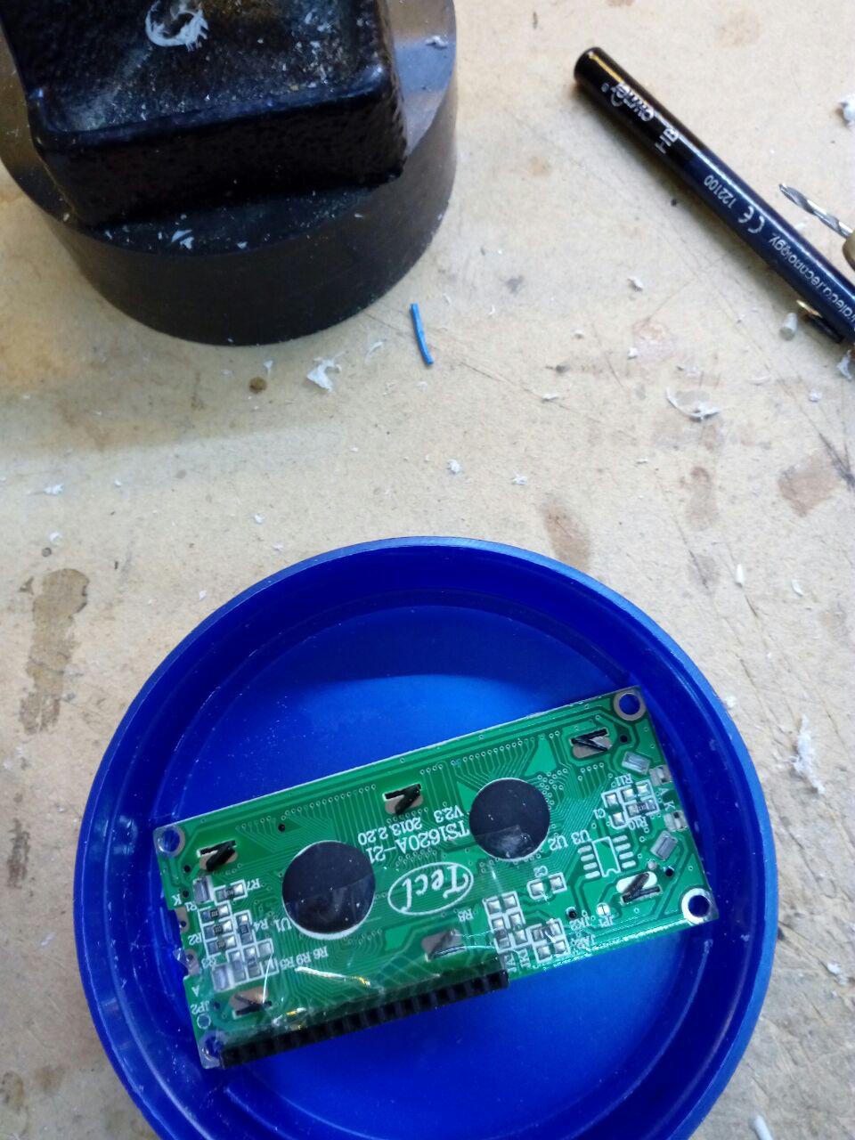
Speedometer circuits. Once we have finished manufacturing our speedometer for bikes we can turn it on. The first time we start it or we do a reset A message with the text "PRESS BUTTON TO START" will appear on the 16 × 2 LCD screen. Pressing one of the Pause / Resume or Display Mode buttons will start the first period / lap.

Simplest Speedometer Circuit for Your Bicycle using a Voltmeter Circuit Diagram
As previously mentioned, the circuit may be calibrated using the 10K setting at pin #5 of the IC in the way shown below. Begin paddling as fast as you can after putting your bike on stand. At the same time, change the preset such that the tenth LED only starts to light up when the bicycle wheel rotates to its maximum. Here we'll see how a simple yet accurate analogue speedometer circuit can be constructed at home using just a single IC and a few external passive components. The speedometer can be universally used with all 2-wheeler, 3-wheeler, even in bicycles for indicating their speeds. Three basic approaches to building a bicycle speedometer circuit will be discussed in this article: By Combining a Dynamo and a Meter. Combining LEDs and the LM3915 circuit. Mixing a magnet and a Hall effect sensor. 1) Using a Voltmeter alone.

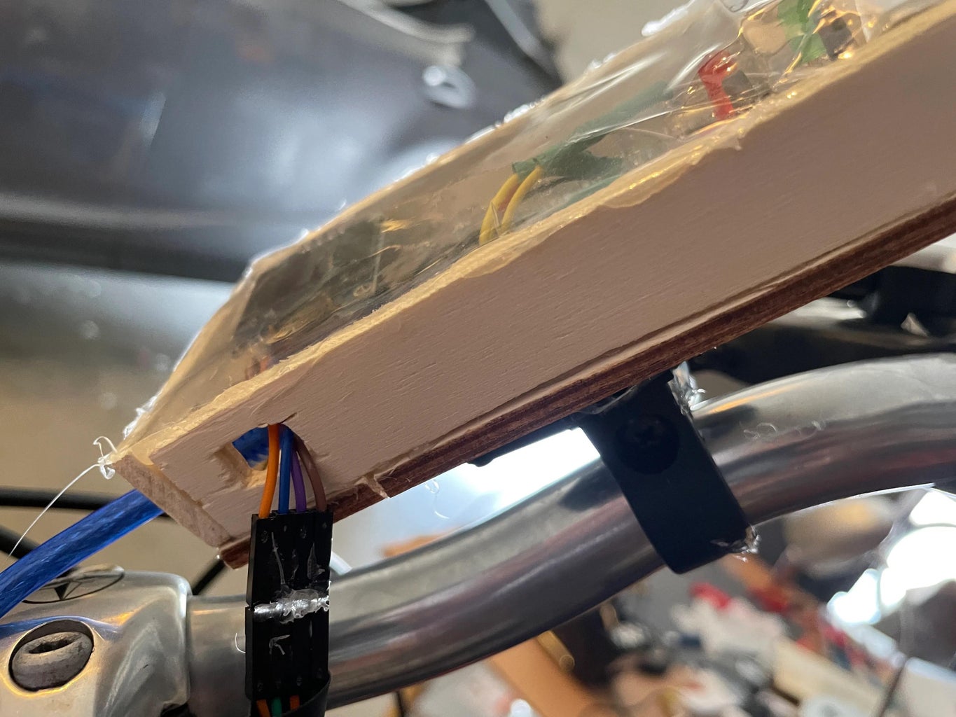
The dimensions of the enclosure are 3.5"x4"x2". I modeled the box in AutoCAD and generated the laser cut files (with finger joints) in Autodesk 123D Make. Then I added two holes for the switches and a rectangular opening for the LCD screen. I also added some holes on the bottom of the enclosure to make attaching it to the bike easier.
