How to Build A Smart Cooling Fan with Arduino Circuit Diagram automatic fan control system based on the Internet of Things (IoT). The system makes use of an ESP32 -based smart fan control circuit that uses Blynk to regulate the speed of a standard fan or other appliances. With the help of the theoretical or quantitative examination of the fan speed control algorithm's effects on the system's
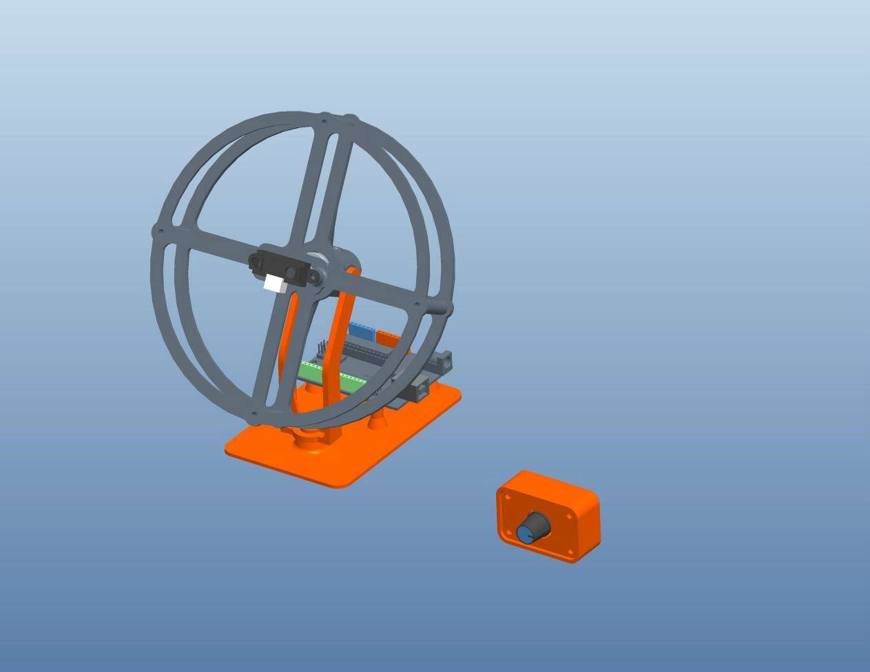
For the fan part, a 12V fan is perfect for this application as it is easy to control the speed with the PWM signal. The 16×2 LCD Display will display the instantaneous temperature and fan speed as well. To get started, you can refer to Arduino Temperature Fan Speed Controller project, which gives overall idea about the working.

Based Temperature Monitoring and Automatic Fan Control Using ESP32 Circuit Diagram
Automatic Speed Control and Turning ON/OFF for Smart Fan by Temperature and Ultrasonic Sensor. A prototype of smart fan was built in this research using ESP8266 as a microcontroller, DHT22 and HC-SR04 are used to measure temperature for speed control and detect the user for automatic on/off respectively. A group of participants used the Arduino Attiny85 Smart Fan Controller: I did. I have many tools that has a fan. And some tool's fan always runs at maximum speed. So I made it more quiet. Step 1: Design, BOM. Its design is simple. But I want to make it really small. So I can put in my tools. Auto_Fan_Controller_V3.1_2Pin.sch. Download. Auto_Fan_Controller_V3.1_2Pin.brd

[4] Room Temperature based Fan Speed Control System using Pulse Width Modulation Technique This paper presents the design and simulation of the fan speed control system using PWM technique based Controlling the Fan Speed and Accessing the Temperature through cloud Technology using DHT11 sensor ", international journal on future Revolution in computer science & communication Engineering volume:4 issue:4.2018. [2] Keeratiburt Kanchanasatian, "Automatic Speed Control and Turning ON/OFF for Smart Fan by
PDF An IOT Based Smart Fan Module Circuit Diagram
After that, you have to create Datastreams. Here I will control 4 relays, so I have to create 4 Datastreams. And for Fan Speed Control 1 Datastream. Steps to add Datastreams. Go to the Datastreams tab. Click on New Datastream and select Virtual Pin. Enter a name, select the virtual pin V1, and the datatype will be Integer. Then click on Create.