Bridge Rectifier Circuit Diagram Types Working Its Applications In a bridge rectifier circuit, two diodes conduct during each half cycle and the forward resistance becomes double (2R F). In a bridge rectifier circuit, Vsmax is the maximum voltage across the transformer secondary winding whereas in a centre tap rectifier Vsmax represents that maximum voltage across each half of the secondary winding.
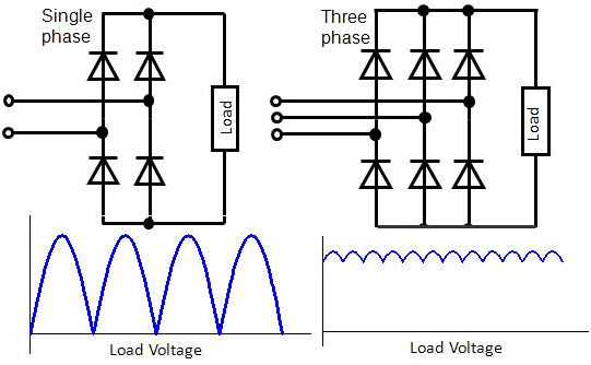
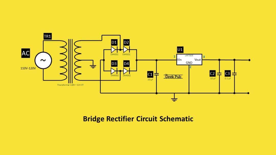
Learn how a rectifier diode works and how it can be used in power supplies to convert alternating current into direct current. Also get a detailed explanation of the three standard rectifier configurations- half-wave rectifier, full-wave rectifier, and bridge rectifier. Also, find out how to build a bridge rectifier circuit through three simple steps. Now, a bridge rectifier on its own doesn't truly convert AC as we found out in the USB charger circuit demo. It only converts AC into a DC wave pulse (or DC oscillation). It requires some capacitors to clean up the pulse and create a more DC like signal. Full wave bridge rectifier is formed by connecting four diodes together in such a way that their arms form a bridge, hence the name bridge rectifier. In bridge rectifier, volatge can be applied to the diode bridge through a transformer or directly through the AC signal without the transformer. Here we are using 6-0-6 center tapped transformer
Full Wave Rectifier and Bridge Rectifier Theory Circuit Diagram
Unlike half-wave rectifiers, which discard the negative amplitude, the bridge rectifier preserves both polarities, classifying it as a full-wave rectifier. A key advantage of a bridge rectifier is that it eliminates the need for an expensive center-tapped transformer, thereby reducing both the size and cost of the circuit.

The full wave rectifier circuit consists of two power diodes connected to a single load resistance (R L) with each diode taking it in turn to supply current to the load.When point A of the transformer is positive with respect to point C, diode D 1 conducts in the forward direction as indicated by the arrows.. When point B is positive (in the negative half of the cycle) with respect to point C
Bridge Rectifier Circuit Circuit Diagram
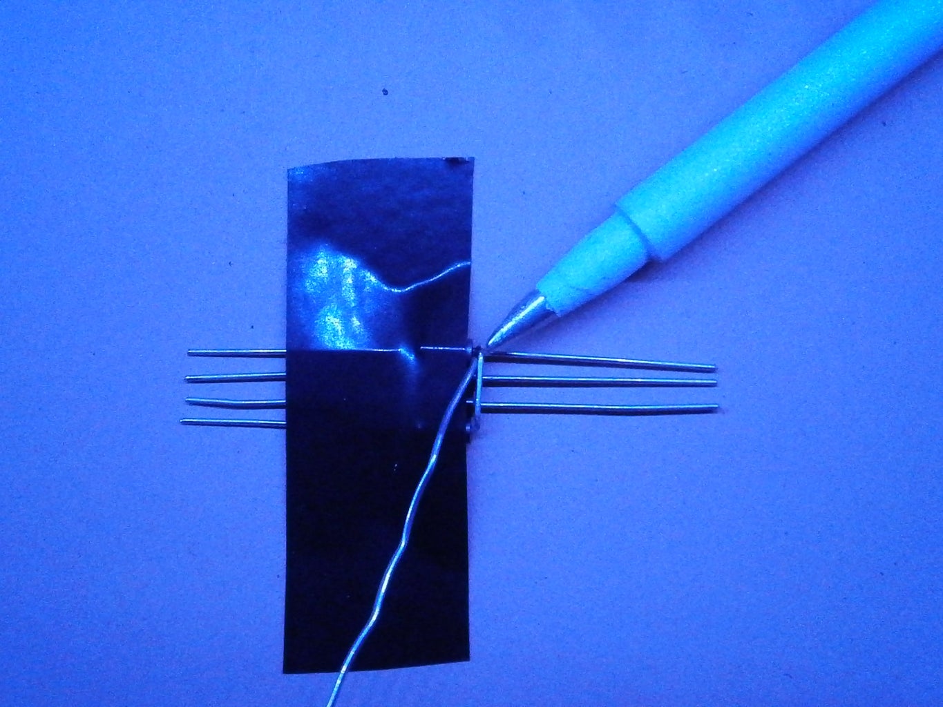
How to Make a Bridge Rectifier Circuit using 1N4007 Diodes. Making a bridge rectifier using four 1N4007 diodes is not at all a difficult task. Simply by twisting the terminals of the four diodes in a specific pattern, a bridge rectifier can be made within seconds. Your bridge rectifier design is ready and may be used for the intended
